Please refer the following instructions of fundamental technical note of a speaker to get great performance out.
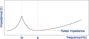
The electric impedance of speaker unit show a normal frequency response indicated in the diagram below. In this diagram, the rated impedance should be set at the "b" point which is the lowest frequency beyond the free air resonance frequency (fo).

The Standard of Rated Impedance are 4Ω/8Ω/16Ω/32Ω. Although the rate impedance could be set based on your requirement, but the characteristics and the input of speaker units may be varied.
The input shall be calculated by the formula as below, based on JIS (Japanese Industrial Standard)
P = V^2/Z
P:Input Power (W),
Z:Nominal Impedance of Speaker Units (Ω),
V:Input Voltage (V)
The rated input is specified to run the speaker units properly. Normally this input is calculated from the voltage by the specified input and the rated impedance, and to be checked by the tests standardized by JIS listed below;
- Operation Test (program source)
- Sweep Test (sine wave)
- Running Test (white noise)
In case of long-time running over the rated input, a thermal destruction by heat of the voice coils or a mechanical fatigue destruction of the suspension system and the lead wire may be occurred. Please take note that these destructions are out of our warranty. If you require higher input than the specified rated input, please consult us.
The maximum input is the permitted maximum input when the speaker units receive extremely short-time signals. This input shall be set as an actual input which does not cause permanent damage when the speaker unit or speaker system are loaded 10 times of 1 minute long signal at an intervals 2 minutes.
This is the variation of the output sound pressure level against the variation of the frequency when the speaker units are loaded in regular voltage, and shows a curve in the graph with a vertical line of the output sound pressure level and a horizontal line of the frequency. The most common characteristic and indicator for judgment of speakers' sound quality, e.g.) the transformation efficiency between mechanical vibration and electric signal, the reproduction frequency range etc.
Normally this shall be specified as a characteristic using by a JIS closed box. Therefore, the actual characteristic may be varied by the capacity, grill size and shape of the cabinet, which is use for the speaker units. From these, we can strengthen that the total sound design including speaker / cabinet conditions is important.
This indicates efficiency of the speaker units, and is calculated from the output sound pressure level of frequency response. This is the average sound pressure of 3 or 4 different frequencies at each provided points.
Specifically, this shows the sound pressure in dB unit (0dB = 20μPa) at 1 meter distance from the speaker unit when input power is 1W. As for small speaker units with less than 1W rated input, an appropriate input power less than 1W should be used and adjusted for calculation of the output sound pressure level.
The frequency response and the output sound pressure level may be varied by the conditions of the anechoic room and the shape of baffle of JIS closed box. Therefore, this characteristic cannot of JIS closed box. Therefore, this characteristic cannot be simply compared with the specifications of other brands.
This frequency is called "fo" and it is occurred by the moving mass of speaker units and the compliance of the suspensions,e.g.)the surround(edge),the spider(dumper). This is an important factor to determine the low limit reproduction frequency of the speaker units.
The fo is known from the impedance characteristic, which is the lowest frequency with the maximum absolute value electric impedance. Based on the JIS standard the fo is provided with the frequency when the baffle is not used. Therefore, it shall be varied by the air stiffness affected by the additional mass of air and the actual cabinet capacity.
The sound quality, sound volume and endurance of speaker units are affected by the way of installation of speaker sets. To use speaker units properly, please follow the instructions stated below.
- Baffle
The clearance in front of the speaker unit depends on the cabinet shape / size you use and the grill shape and installation method of speaker unit. Therefore, you are required to check the clearance each time when you install the speaker units. Especially, there may be some buzz sound because of interference of the grill with the cone paper in case of not enough space between the cone paper and the grill baffles. To avoid this, you are required to be careful for designing speaker cabinets. - Surroundings
The speakers are magnetic unit, so they may draw metal pieces or screws within it. Especially, solder wastes or lead wires may cause some noise when it attaching with the cone paper. To avoid this, please keep the surroundings of the speaker units clean. For micro speaker, please do not pile up each speakerunit or touch the front cone paper by some metal piece. These may cause damages of the voice coils and the lead wires, deformation, disconnection of wires, buzz sound and low sound. - Cabinets
The performance of speaker is depends on the installation conditions. A big size cabinet within permissible range is preferable to be set for speaker, and it is not encourage to cover some obstacle or thick clothes in front part of the speaker. Also, to cram the rear of speakers by the PCB parts or some gap / holes between the speaker and baffle may affect the reproduction of low range sounds. - Frames
When you install the speaker units, please pay attention to load the frame equally. The installation of speaker unit by pushing the frame partially may cause deformation of the frame or cone papers and thus it may produce abnormal sound. - Soldering
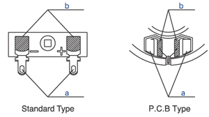
In the case of soldering the terminal rug, please solder in prescribed areas only ("a" in the lower chart), and do not solder to the areas "b" in the lower chart, which may cause looseness and unfastening of the lead wires, abnormal sound and disconnection of the lead wires. Please make sure that soldering should be done to the prescribed area in a short time. (Recommended condition: 350±2℃/2 sec)

- Voice Coil
To avoid the dissociated corrosion, please do not load the direct current electrical to the voice coils. It may cause disconnection of the voice coils wire. Especially, for thin voice coils wire or usage under high humid conditions, it may cause serious problems. - Others
There are many other precautions when you install the speaker units. You may contact us for more details information.


